
In modern industrial cooling systems, co
How to Calculate Cooling Tower Fill Volu
When the Original Cooling Tower Fill Is
When replacing cooling tower fill, engineers often spend most of their time checking width, length and fill height. Those dimensions are necessary, but they do not completely describe how the fill will sit inside the tower.
There is another practical question that is often overlooked: where will the joints between fill sections actually be located?
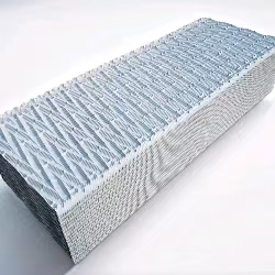
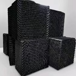
For honeycomb Cooling Tower Media, this can be important because the fill is not installed as one continuous piece in every tower. Large fill areas are commonly divided into sections that have to work around internal supports and installation access.
Imagine an installation area that requires a relatively large overall width.
One approach may use one large section. Another may divide the same area into two or more sections. On paper, the total width may be almost identical.
Inside the tower, however, these two arrangements are not identical.
The position of the joint changes. The number of interfaces changes. The location of the support points can also change.
This is why a Multi-Specification Cross Flow Cooling Tower Fill solution can be more useful than simply choosing the largest available section.
In a cross-flow tower, air enters through the side of the fill area while water moves downward through the fill.
This means that the physical arrangement of the fill sections exists directly inside the air and water path. The joint between two sections should therefore be considered together with the surrounding tower structure rather than treated as a purely mechanical connection.
A specific configuration such as 1010mm-2500mm Cross Flow Cooling Tower Fill illustrates why both dimensions can matter when planning a replacement.
The 1010mm dimension describes one part of the physical configuration, while the 2500mm length determines how the section occupies another direction of the tower. Changing either dimension can alter where section boundaries appear.
On a job site, it can be tempting to divide the fill wherever it is easiest to handle.
That may save time during installation, but the division should still make sense inside the tower.
A joint located directly against a structural member may behave differently from a joint positioned inside an open fill area. Similarly, dividing a section around an access opening may be more practical than trying to move one large block through a restricted entrance.
That is why Dual-width Adaptable Cross-flow Fill can be relevant in towers where one fixed width does not describe every section of the installation.
Modular fill installation does not mean that the blocks can be arranged arbitrarily.
A good modular arrangement still follows the tower's physical geometry. The fill sections should occupy the intended area, meet the surrounding supports properly and avoid creating unnecessary dead spaces.
This is particularly important in older towers where previous modifications may already have changed the internal layout.
For a practical site survey, it is useful to record the location of supports, access openings, existing block boundaries and the actual dimensions of each fill section.
Do not record only the total fill area.
The total area tells you how much space exists. The section boundaries tell you how the space has actually been used.
For honeycomb Cooling Tower Media, that distinction can make the difference between a replacement that simply fits on paper and one that is straightforward to install in the real tower.
Cooling tower fill media updates and technical insights for global industrial clients.
In modern industrial cooling systems, cooling tower fill plays a critical role in improving heat exc

Why the Joint Position Can Matter as Much as the Honeycomb Fill SizeWhen replacing cooling tower fil
Contact our team for cooling tower fill media details, quotations, and project support.
Chat on WhatsApp